
LEARN SOME TECHNOLOGY TRICK
dimixywap.com

From http://www.dimixywap.com
A little soldering is all it takes to make this cool little emergency cell phone charger. Keep it in the glove box of your car, in case you ever get stranded in the woods and start to hear banjo music!
You might be able to find the mini solar panels at a store that sells science or electronics equipment; otherwise you can order them online. Please note, you'll also be cutting the wire on the cell phone charger, so make sure it's not the only one you have! You can often find cheap chargers at discount stores like Big Lots -- it doesn't matter if it's AC or car compatible, since you'll only be using the end that plugs in your phone.
MATERIALS:
1 Altoids Tin case
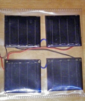
2 Mini Solar Panels (3V 20mA each)
1 Solder (3")
1 Small Heat Shrink Tubing (4")
1 Large Heat Shrink Tubing (4")
1 Double Sided Tape (3")
1oz Flux
1 Solder Iron
1 Heat Gun
1 Wire Stripper
1 cell phone charger
Step 1: Step1: Cut wires & tubing

Take
the 2 solar power panels and cut all four wires to about 1" in length.
Cut 1/4" of plastic off of the tip of each wire with the wire stripper
so copper wires are exposed. This exposed wire is called a 'lead.' Cut
the small heat shrink tubing into four equal pieces (1" each). Slide the
small heat shrink tubing onto both black wires.
Ads not by this site
Step 2: Step 2: Solder solar panel leads

Step 3: Step 3: Heat-shrink tubing

Slide
small heat shrink tubing over the leads you just soldered together.
Heat the tubing with heat gun just enough for it to shrink.
Ads not by this site
Step 4: Step 4: Cut phone charger wire
Cut
off the wire from your old charger to about 2.5 feet and strip off 2.5"
of outer plastic from the loose end. Cut 1/4" off of each of the inside
wires to make leads. Slide the full length of the large heat shrink
tubing onto this main wire for later use in Step 6
Ads not by this site
Step 5: Step 5: Flux, solder and heat-shrink loose leads


Step 7: Step 7: Heat-shrink solar panel leads

On
your main wire, slide large heat shrink tubing over the two soldered
leads which connect to the solar panels. Use the heat gun to shrink the
tubing.
Ads not by this site
Step 8: Step 8: Tape and close
On the back of the solar panels, cover the two brass rivets with double-sided tape (so they don't make contact with the Altoids tin.) Tape the two solar panels on the inside lid of the tin. Tuck the main wire into the case and close. Go somewhere sunny (Florida is nice) and charge it up!

Ads not by this site
Portable, lightweight, waterproof and can be positioned in 3 ways:
1. Position it in 45 degree angle, facing the window up to a meter away, if indoors. You just have to experiment a bit, if it doesn't charge, move it closer to the window and if you are after quick charge, it is good idea to set mob to energy saving mode I think.
2. It can be attached to the bag or ruck sack, by placing leg in a pocket with your phone plugged in, so you can charge while out and about.
3. Can be hung on the window with the string, so even in limited light you can still get charge.
Kit list
- 2 x Flexible solar panel 0.8W, 2V
- DC-DC step up converter charger with USB female DC 2.5V-5V
- 6 x sugru minipacks
- Soldering iron
- Some solder
- Red and black wire
- Wire stripping tool
- Voltmeter
- Tubing, like irrigation pipe or a straw, something similar, not too bendy as it needs to support the panel, 2 x 11-12cm long
- Pill box
Step 1

When choosing solar cells for this
application, make sure it has a decent current and voltage of 4V or 5V
even better if you planing to use it indoors more, this way you can
still charge in darker conditions, in addition to this to achieve 5V
needed to charge, the dc voltage booster is necessary, I've chose
2.5-5V, so if your 4V panel only produce 2.5-3V its enough to charge, so
it doesn't have to be in direct sunlight. To increase current you need
to connect cells in parallel, to increase voltage connect in series. For
the 2 panels I have I need to increase voltage, so if you getting same
panels you need to connect them in series to achieve 4V and the current
is high enough.
Step 2
Ads not by this site

First measure voltage of your solar
cells to check if its the same as in manufactures/sellers specs, this
gives you a chance to check the distance from the light source ( window)
and before soldering test polarity of the cells to determine the
positive and negative (+ and -) when your voltmeter shows minus - you
have it wrong way round, just switch it round and just like on your
voltmeter you have black and red wire, solder wires about 15cm long in
same way red to plus, black to minus and to connect your the cells in
series you need to solder short peace of wire from + to - ( doesn't
mater what colour) Then you need to connect solar panel to the charger
module in the same way solder red to plus and black to minus and before
you do that don't forget to stick tubing on wires, if you would be using
this.
Tip: (if you are not familiar with soldering) put a drop of solder on the clean surface first then add wire, I would advice practice before soldering panels, I haven't solder myself for long time, but i did not practice, thats why my joints on cells don't look too good, so its good idea to practice before, but don't worry if it doesn't work out very nice, it will still work. Also you need to strip wire before soldering.
Tip: (if you are not familiar with soldering) put a drop of solder on the clean surface first then add wire, I would advice practice before soldering panels, I haven't solder myself for long time, but i did not practice, thats why my joints on cells don't look too good, so its good idea to practice before, but don't worry if it doesn't work out very nice, it will still work. Also you need to strip wire before soldering.
Step 3

Ads not by this site
Now place sheet of cling-film on your preferably flat work surface and form some sugru with your hands and apply, start from middle, make a thicker strip, add sides by rolling a thin sting and attach, thickness depends on the cell, they can vary dramatically, apparently made by hand, but the idea is cover white surface from the front and the back insulate wires and joints, attach string for hanging option. Eventually attach/secure ends of tubing to panel and the box. Leave it to set for 24h and the cling-film prevents it from sticking to surface, it can be easily pulled off.
Tip: If you find it difficult to do it all in one go, do it in sections, leave to set then do another section.
PS: you can attach string to the top rather than bottom, up to you...
We had joy, we had fun
|
Product: True
Genre: True
by krrish ibrahim
 |
But, oh no! Clumsy oaf that I am, one of those cheap solar powered garden lamp things rolled off the deck and cracked the plastic dome. Catastrophe.
But the wife says, “Those things are rubbish anyway. I was thinking of chucking ‘em.” Immediately my inherent Yorkshire sense of thriftyness kicked in, and I salvaged those four rubbish garden lamps to see what other uses China’s finest engineering could be put to.
Here’s the result of that afternoon’s tinkering - a portable emergency mobile solar charger that fits inside Pocket Gamer’s favourite see-through container, the CD slip case.
This does take a bit of soldering, and if you get it really wrong (and I mean really wrong) you could do your phone harm, so be warned. Most likely, though, getting this wrong will only mean a waste of time, so don't be too worried.
Anyway, here’s one we made earlier.
| This is our solar powered garden light before we start to butcher it. You might need a bit of extra willpower to get into it - ours had one or two screws and a lot of glue holding it together. |  |
| But
it couldn’t stop us in the end. Cut off the wires connecting the small
solar collector to the circuit - one at a time in case there’s any power
in the battery. Note that even if there is power in the battery, it’s not enough for you to feel it, but you don’t want to harm the solar collector. Our solar cells were stuck down with sticky pads, so be careful not to snap it when taking it out. |  |
| Holding
it up to the light shows an output of 1.8v from a single cell, and this
is indoors and not even in particularly bright daylight. Gather up all four of your solar collectors, and test each one just to be sure it’s working and putting out around 2V - hopefully nearer 2.5v in direct, bright sunlight. |  |
| We’re
now going to wire two of them up in series. This means connecting the
positive terminal of one cell to the negative terminal of another. A
serial configuration adds the two voltages together, giving us an output
between 4 and 5v. Wire up the other pair of solar cells the same way, so you’ve got two pairs of cells wired in series - each putting out around 4 - 5v. |  |
| The
only other component this charger needs is a diode. This prevents
current flowing from the phone's battery back into the solar panels. We robbed the diode from the small circuit inside the garden light. The diode will look like a small black cylinder with a white band around one end (kind of like a Duracell battery). If you need to buy one, ideally you want something like an N5817, which is a Schottky diode. These are better because they have a lower forward bias. A standard diode (N4001) drops the voltage by 0.6v, while the Schottky diode only drops it by 0.2v - and that can be the difference between charging and not charging on such low current applications as this. |  |
| Next we need a connector. We’ve gone for a USB extension cable, as most devices these days will charge from a USB connection. Cut the plug off, leaving around 10cm of cable on it (more on this in a few minutes). The socket end will be longer, so strip it back to expose the wires inside. The colour of the data wires often varies, but you’ll pretty much be guaranteed red and black for the power connections. |  |
| Solder
your diode to the positive terminal on one of your pairs of
series-wired solar collectors. The white band on the diode should be
AWAY from the solar panel’s terminal. Solder the red wire from your USB socket’s lead to the other leg of the diode, and the black wire to the negative terminal on the OTHER pair of solar collectors. |  |
| The
next thing we need to do is wire up the two pairs of solar collectors
in parallel (as opposed to series). Wiring them in parallel doubles up
the current, but leaves the voltage of 4 - 5v the same. Solder a wire from the ‘empty’ positive terminal of one pair of solar panels to the positive terminal on the other pair. Then take a wire from the negative terminal of one pair of solar panels to the negative terminal of the other pair. Our wires cross over here because we didn’t want to strip back too much of the USB cable to reach between the positive and negative terminals of the two solar collectors. Sorry if it looks a little untidy and/or confusing. |  |
| Next
we put some double sided sticky tape on the back of each collector and
stuck them inside a clear CD slip case for a bit of extra
weatherproofing. We also stuck a bit of extra tape where the USB cable leaves the CD slip case, to prevent us from accidentally pulling on the soldered connections. |  |
| Now
to test it. Take the USB plug you cut off the lead (the one with 10cm
of cable left on it), and strip it back so you can get to the red and
black wires. Plug it into the USB socket attached to your solar collectors, put it into direct sunlight and check you’re getting 4 - 5v output. As you can see, we were getting 4.23v without even going outside. Nice. |  |
| And
you’re finished. We tested it out on a Bluetooth headset and an MP3
player - both of which happily charged with sunlight through the window.
We even gave it a shot with our G1, which set off charging straight away (see the orange light and small power symbol at the top right of the screen). Don’t expect this to charge your gear quickly (it’d never give a G1 a full charge, for instance), but as a very portable and light emergency backup to give you a little extra juice when you really need it, or to extend your standby times, this could be a life saver. One final quick tip: to get some juice into your phone a little quicker, switch it off when you put it on charge | |
A SOLAR POWERED MOBILE PHONE
by krrish
ibrahim


I WILL SHOW YOU HOW TO ADD A SMALL
SOLAR PANEL TO A PHONE SO IT EXTENDS THE LIFE OF YOUR PHONE BATTERY.BECAUSE OF
THE TYPE OF SOLAR PANEL I USED IT LOOKS GREAT AND DOES NOT GET IN THE WAY OF
USING THE PHONE NORMALLY AND YOU CAN STILL USE YOUR MOBILE PHONE PROTECTIVE
CASE IF YOU USE ONE BECAUSE OF THE TYPE OF PANEL I HAVE USED.MY NEXT
INSTRUCTABLE IF I DO IT WILL BE USING THE SAME METHOD TO ADD A SOLAR PANEL TO A
A LAPTOP TO INCREASE ITS BATTERY LIFE AND TOP UP THE BATTERY WHEN YOUR NOT
USING IT.
PS THIS IS MY FIRST INSTRUCTABLR AND ALSO I TOOK PICTURES AFTERWARDS AS I SUDDENLY REMEMBERED THIS SITE.AND ALSO I HAVE NOT STUCK THE SOLAR PANEL DOWN YET THATS WHY IT LOOKS RAISED ABOVE THE CASE.I HAVE NOT GOT ANY DOUBLE SIDED STICKY TABE.PROVIDING YOU SOLDER IT OK THEN IT WILL BE FLUSH WITHT HE PHONES SURFACE.
THANKS PLEASE COMMENT AND ALSO TAKE A LOOK AT THE LAST STEP IT GIVES YOU SOME COOL IDEAS IF ANYONE WANTS TO MAKE THEM

I BUY MY PANELS FROM : http://www.selectsolar.co.uk/pics/SP3-37%20(22mA%20at%203v).php
THE LINK ABOVE IS THE PANEL I PARTICULARY USED. THE REASON I USE THIS PANEL IS BECAUSE IT PROVIDES THE RIGHT VOLTAGE FOR MOBILE PHONE BATTERIES AND IT IS PAPER THIN AND IT HAS A MIRROWED FINISH SO IT DOES NOT LOOK UGLY ATTACHED TO YOUR PHONE.
THE PANEL IS 22MA @ 3VOLTS AND MEASURES JUST 3.7cm by 6.4cm
more info ont his panel here:lightweight, paper thin and durable
flexible enough to curve around an object 3 inches in diameter
will not break if dropped
wide range of sizes and power configurations available
thin profile enables them to be easily integrated with devices for solar recharging or direct power
Ideal for recharging AA, AA, 6V and 2V batteries
Please note: these modules do not have a UV stabilised surface.
Simple to connect - just solder or crimp to the copper tape.
Size 3.7cm by 6.4cm.

with most phones it is easiest to
mount it on the back of the phone as thats where you have the most surface area
free and also the back does slide of to allow access to the battery.
you must decide where to put the panel first so you know where to cut the 2 very small holes in the case.
you must decide where to put the panel first so you know where to cut the 2 very small holes in the case.

now you must find a place to mount
the blocking diode.i mounted mine in the plastic casing between the battery and
the case.but if you want you can take the phone apart and mount it inside
somewhere but you must insulate it so it doesnt short andything out.also
conside where you mount it you must allow access for small wires from the solar
panel and the battery. IF YOU FOLLOW MY INSTRUCTABLE THEN THE WAY TO INSTALL
THE BLOCKING DIODE IS AS FOLLOWS. the white strip on the diode need to face the
battery wire.the whote strip acts as a gate and will not let power from the
battery pass through it.but it must be nearest the battery wire. if thre strip
is nearest the solar panel wire then you wil only discharge your battery and
not charge it.ps ue a dremel if you have one as i used a soldering iron to melt
the plastic and it loks messy. i do aactually have a dremel but didnt think to
use it here for the whole for he blocking diode. lol

i used very thin video cable the
type you would use to connect a ccd/cmos camera to a power supply and screen

solder the the red wires to the
blocking diode please remember before you cut the wires to leave enough length
so the wires will reach the battery and the panel. be carefull not to heat up
the diode over 150c otherwise it will be useless if it gets to 200c approx.and use
least amount of solder as you can so you dont have any problems fitting the
diode in the phone.

neatly hide the wires and the diode
in the phone casing and then connect the wires using the twist method onto the
connectors on the phone where the battery touches them.red for positive and
black for negative.


now earlier on you decided where to
mount the solar panel so you now need to get the wires from the inside of the
phone to the outside so you can attach the panel.hold the panel in place then
decide where to cut the holes.
remember you must allow enough play on the wire for when you take the case of to access you simcard or something.
you can cut the holes using very small circuit board drill bits or use a stanley blade or hooby nife or even heat up a needle on a soldering iron or with a lighter and burn a whole through you phone case,if you burn a hole you need to use a stanley blade to trim it flat.


solder each wire to the panel
remember you have to scratch of the plastic coating on the copper strips before
you solder it and dont melt the panel solder as quickly as you can and try and
solder it flat so its not raised above the phone case when you mount the panel.
you can find the polarity of a soalr panel by hooking it up to a multimeter. my multimeter displays a minus sign if i have it in reverse polarity.some other multimeters just diplay 0.00 volts if you have the polarity wrong,so just switch the probes round and attach to solar panel and it should give you volts.
we dont need a voltager regulator as its a very small solar cell and it cannot harm your battery
simply use double sided sticky tape
to mount the panel to the phone. is suggest you apply the tape only to the
removable back case of the phone so you can get access to your battery and
simcard etc.
Step 10: Another way of doing this without cutting holes in
your phone or anything and some other cool ideas i have with solar panels
instead of adding a panel to your
phone what you can do is get a protective phone case like in the picture
below.mount the panel inside the phone case, now all phones have a charger
point usually at the bottom of the phone all you do is connect the solar panel
to the end of a phone charger but put a blocking diode in between the panel and
the charger end. then just plug the chargeing tip into the bottom of your phone
and it charges. it may not register as charging as its low ma's but it will
charge your phone.if you think that it is not charginf your phone then you can
put a 200k resistor on the ground connection between your panel and your
charger plug.also phones that have a mini usb connection on them sometimes
require you to connect the data- cable to the ground for it to register that a
cable is plugged in to it.you can search for pinout diagrams on the internet
for your specific phone.but as we are dealing with low power solar panel the
phone will never register as charging as its too low to detect it, but i can
tell you it will charge yourphone regardless what way you do it.
if you want to do something else similar then you can buy a bigger version of this paper thin mirrowed finish solar panel and attach it to the back of your laptop screen so it charges your battery when your not using it and when you are using it.and if you wanted to go the whole hog you could even buy long thin solar panel strips and insert them inside your screen where the florescent tube is which lights up the screen and collect free energy that way and put it back itno the laptop battery.or use it to power usb sockets etc.or even connect a female usb cable to the soalr panel on the back of your laptop screen adn use it to charge mp3 palyers and things instead of using the usb socket on yout laptop.
if you want to do something else similar then you can buy a bigger version of this paper thin mirrowed finish solar panel and attach it to the back of your laptop screen so it charges your battery when your not using it and when you are using it.and if you wanted to go the whole hog you could even buy long thin solar panel strips and insert them inside your screen where the florescent tube is which lights up the screen and collect free energy that way and put it back itno the laptop battery.or use it to power usb sockets etc.or even connect a female usb cable to the soalr panel on the back of your laptop screen adn use it to charge mp3 palyers and things instead of using the usb socket on yout laptop.
No comments:
Post a Comment